Television system
There are three types of TV systems in the world. One is the NTSC (COLOR) and EIA (B/W) systems, adopted in Japan and the United States. The other two are the PAL (COLOR), SECAM(COLOR)and CCIR(B/W)systems that are adopted in Europe. The big differences between the systems are the number of frames (frame/sec) and scanning lines.
1) U.S.A., JAPAN, etc. (525 scanning lines)
NTSC (National Television System Committee) ・・・・ Color
EIA (Electronic Industries Association) ・・・・・ B/W
2) The area of west Europe. (625 scanning lines)
PAL (Phase Alternating Association) ・・・・ Color
CCIR (Comité Consultatif International des Radio Communications) ・・・・ B/W
3) The area of France, Russia and east Europe.(625 scanning lines)
SECAM (Séquential Couleur á Mémorire) ・・・・ Color
(Various Television Systems)
| TELEVISION SYSTEM | NTSC (Color) | EIA (B/W) | PAL (Color) | CCIR (B/W) | SECAM (Color) |
| Number of scanning lines (TV lines) | 525 | 525 | 625 | 625 | 625 |
| Number of frame (f/s) | 30 | 30 | 25 | 25 | 25 |
| Interlace | 2 : 1Interlace | 2 : 1 Interlace | 2 : 1 Interlace | 2 : 1Interlace | 2 : 1Interlace |
| Horizontal scanning frequency (KHz) | 15.734 | 15.75 | 15.625 | 15.625 | 15.625 |
| Vertical scanning frequency (Hz) | 59.94 | 60 | 50 | 50 | 50 |
| Video frequency bandwidth (MHz) | 4.2 | 4.2 | 5.5 | 5.5 | 5.5 |
| Color subcarrier frequency (MHz) | 3.58 | 4.43 | 4.75 |
Scanning Line
Scanning horizontally from top to bottom makes a TV picture. The total number of these horizontal lines is defined as “number of scanning line.” NTSC/EIA consists of 525 horizontal lines, and PAL / CCIR / SECAM is 625 lines. Actually, scanning is not once per frame but twice interlaced, therefore scanning every other line makes full screen. The 525 lines of NTSC/EIA are separated into even and odd numbers, and scanned twice to produce one screen.
The NTSC/EIA Scanning time for 1 field is 1/60sec. One screen consists of two fields (odd/even), and two fields combined make a “Frame.” That is, the scanning time for 1 frame is 1/30sec. The reason for interlace scanning is to reduce video bandwidth and decrease flicker.
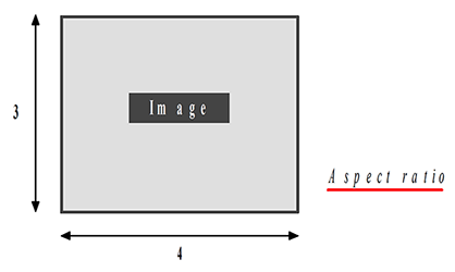
Aspect Ratio
Aspect ratio is the ratio of TV screen width to length. The aspect ratio for an ordinary TV screen (NTSC,OAL,SECAM system) is 4:3.
Color Signal
This is a kind of signal, which controls chromaticity for Color TV picture. The color signal splits them into various components, complying with each system, and controls them. The NTSC system splits the signal into luminance and chrominance. The signal produced by a color camera consists of the three primary colors R(Red), B(Blue), and G(Green). By combining these three signals at a following rate, it can get a luminance signal equivalent to B/W TV.
Y= 0.3R + 0.59G + 0.11B
To gain color TV signal, R-Y signal and B-Y signal will be transmitted along sub-carrier with luminance oscillating signal by frequency multi-channel telegraphy. The principal purpose of this system is to transmit luminance and color signal without any interference, by setting video signal bandwidth within 4.2 MHz.
CCD CAMERA
CCD (Charged Coupled Device) image sensor
Charged Coupled Device that converts optical signal to electronic signal. CCD is composed of photodiode arrays that produce electric charges according to strength of optical signal and the register part that transfers the electric charges to vertical and horizontal directions to read them out as signal voltage. A device that uses CCD in the register part is called CCD image sensor and is often called simply CCD.
Frame Storage
Frame storage is a system that reads out photoelectric conversion signal. It reads out only odds field line signal in one field and even line signal in the other field line. The exposure time is counted as one frame.
Exposure time=1 frame(NTSC: 1/30sec.)
Field Storage
Field storage system exposes in one field period and reads out combined photoelectric conversion signals of adjacent two lines in order to compensate the reduced signal level, which becomes a half of the signal level of frame storage, resulting from a half of the exposure time of frame storage system. The system changes the combination of the two lines at each field to adopt to the interlace methods.
Exposure time=1 field(NTSC: 1/60sec.)
Interline Transfer CCD
The signal charges of photo sensors are simultaneously transferred to the vertical register at periodical timing and shifted in vertical register one by one at every horizontal period. This system reads out all of the horizontal pixels at the last stage of the vertical register.
Progressive Scan CCD
Progressive Scan CCD is an image sensor that has two readout methods; (1) Read out photoelectric converted signal equivalent to one frame signal in one field period through two independent registers for each field. (2) Read out photoelectric converted signal equivalent to one frame signal in one frame period as non-interlace signal. In ordinary CCD image sensor, two field image signals that have one field exposure timing difference are used to form one frame signal, which results in blurring. Since Progressive Scan CCD reads out picture information from all pixels in one field period, a camera that uses this CCD is effective in taking a still picture without causing blurring.
Effective pixels
Total number of the photodiode arrays on the chip of CCD image sensor are called total number of pixels, while the number of photodiodes which contribute to the actual image signal is called effective pixel number. The periphery of a photodiode array has optical black that is the standard for the black level and this area (about 10% of the total number of pixels) is not included in the effective pixels.
Composite Signal
Color video signal consists of video signal (included Color Signal), horizontal/vertical synchronizing signal, horizontal/vertical fly-back signal (blanking interval), and color burst signal. These are collectively called “Composite video signal.”
| Note | VBS(Video Burst Sync): Composite Video Signal(Color) |
| VS(Video Sync): Composite Video Signal(B/W) | |
| 1Vp-p | An amplitude value(peak to peak) of the video and sync signal defined by a specification. |
| 75Ωtermination | Input impedance of the video signal |
Y/C Output
Output format of the color picture signal, separating luminance signal (Y) and chrominance signal (C). The luminance signal contains the composite sync signal, and chrominance signal contains the color burst signal. When input into color monitor, the composite signal is separated into luminance signal and chrominance signal. This may narrow the luminance signal bandwidth. When Y/C separated signal is input, the horizontal resolution becomes better because the separating circuit for color monitor is not used.
Sync System
When picture signal must be synchronized with an external system, the sync signal of the system is supplied to a camera to synchronize with its picture signal. This is called external synchronization system. There are two external sync signals supplied from outside, composite sync signal system and HD/VD signal (Horizontal/Vertical Drive) system. The operation with internal sync signal generated in a camera irrelevant to the external signal is called internal sync system.
*Line Lock(Power sync system)
A system to synchronize the power source frequency and the TV field frequency without utilizing a Sync generator or cables for external sync. It is available when both TV field frequency and power source frequency are same.
(Example; TV field frequency 60Hz(59.94Hz)=Power source frequency at a 60Hz region.)
AGC (Automatic Gain Control)
AGC automatically controls amplifier gain to prevent the signal saturation when the input light is strong, and increases gain to the regulated level to maintain the appropriate signal level when the input light is weak. It enables to take pictures with fixed lens iris from dark to bright place within the limited range.
AE (Automatic Exposure)
Automatic exposure function detects the brightness of the photographic subject to adjust the iris of lens and shutter speed automatically.
Gamma correction
Cathode-ray tubes generally used for TV have non-linear electric-light conversion characteristic which is expressed as Gamma = 2.2. In order that the optical input level to a camera proportions to the light emitting level from cathode-ray tubes, the picture output signal from a camera must be compensated. The Gamma compensation that is equals to 0.45 must be made for the output signal of usual CCD camera.
A combination of CCD Camera and Standard TV γ= 0.45
A combination of CCD Camera and Image Processing Board (density analysis) γ= 1
*In the event of grabbing images from a camera by a grabber board or other appropriate equipment for the purpose of an analysis of density, the gradation correction (Gamma correction factor = 0.45) is not available.
DSP (Digital Signal Processing)
Against the conventional analog signal processing, a camera uses digital signal processing circuit with A/D (Analog to Digital) converter to obtain picture signal. The camera provides various picture outputs including analog signal and a variety of formats of digital signal. Generally, the signal is processed in analog format from the output CCD image sensor to correlated double sample hold circuit and AGC.
Merits for equipped DSP
1) Smaller camera: Due to miniaturization technology of the substrate circuit
2) High quality consistency: Reduction of inconsistency under a manufacturing process in a mass production.
3) Improvement of the image quality: Greater IC chip density of DSP allows reduction of signal noise and precise image adjustment under a DSP parameter
S/N Ratio (Signal-to-Noise ratio)
The ratio between signal and noise, and the higher S/N value represent the less noise and higher quality picture.
Electronic Iris / Electronic Shutter
In order to maintain the CCD output level within a certain range regardless of the input optical level, the time to store electric charge is changed per each frame.
| Electronic Iris = Changes the storage time for the electric charge |
| Electronic Shutter = Fixes the storage time for the electric charge |
Long-term exposure
Enable the high sensitivity shooting with longer electric storage time (several fields) of the CCD. This is effective for the motionless object.
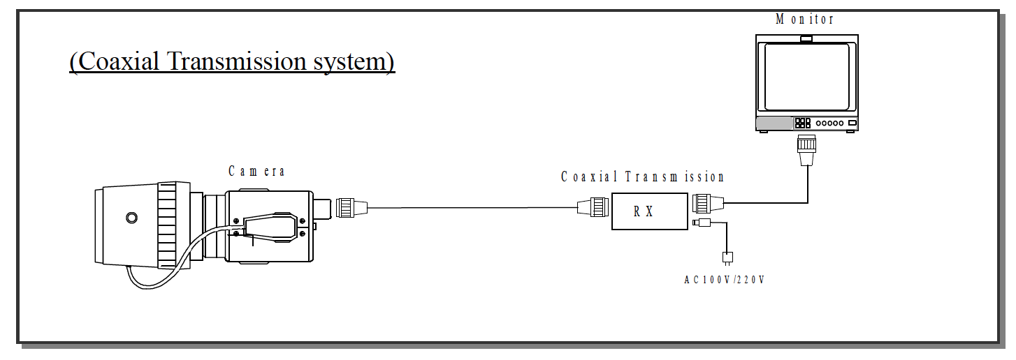
Coaxial transmission system
This system permits the video signal and DC power to be transmitted in the same cable. This method reduces installation costs and improves function by transmitting power and video signal on one cable.
Minimum Illumination
Minimum Illumination stands for a limitation of the illumination that can confirm on a monitor TV while CCD camera is shooting an object. The unit is Lux=lx. In reality, more enough illumination over the camera performance is required to gain appropriate pictures.
| Illumination | |
| Daylight | 10,000 lx. |
| Cloudy sky | 1,000 lx. |
| Indoor (with light from the outside) | 500 lx. |
| Indoor (without light from the outside) | 100 lx. |
| Dusk | 2 lx. |
| Moonlight | 0.01 lx. |
| Starlight | 0.001 lx. |
White Balance
We often regard the subject as a different chromaticity under sunshine and incandescent lamp. This is caused by adaptability to the color temperature. However, basically people can identify the white color as “White” due to their high adaptability to the color temperature. On the contrary, CCD does not have its adaptability and the subject color depends on the light source. Therefore, color camera must be given a correction because the color temperature differs under each light source. White Balance enables re-production of a “White Subject” as “White,” not depending on the kinds of light source.
The camera has the following white balance function.
1)Auto White Balance
The white balance is automatically adjusted on the monitor screen in various lighting situations.
2)Preset White Balance
a. Daylight mode (≒6300°K)
The white balance is adjusted when sunlight is illuminating the monitored area.
b. Fluorescence (≒5100°K)
The white balance is adjusted when fluorescent lamps being used emit light close to the blue spectrum.
c. Fluorescence (≒4200°K)
The white balance is adjusted when fluorescent lamps being used emit light close to the red spectrum.
The white balance is adjusted when incandescent lighting is illuminating the area.
3) P.W.B (Push rock White Balance)
The white balance is corrected in conditions when the above preset modes are ineffective due to extreme color temperature situations.
Backlight Compensation
This is a function that prevents the subject from appearing as “Black Subject” on a display, when it is a back lighted or high-luminance subject.
Backlight Compensation procedure for each camera is as follows.
| ①Gives the Backlight Compensation by applying an adjustment of Electronic Iris and AGC operation. |
| ②Gives the Backlight Compensation only by applying AGC operation. (Fixed-shutter speed) |
| ③Gives the Backlight Compensation by applying Electronic Iris operation. |
| ④Gives the Backlight Compensation by changing the control level for Iris Connector. (Adjust Iris signal to decreasing direction under the backlight condition.) * Backlight Compensation shall be performed only in the combination use of Auto iris lens. |
Lens
The lens is the most important part of the Camera. In addition to proper camera selection, the lens must be selected in accordance with the purpose and site condition.
| *Check points for selecting lens | |||
| a) What dimension (inch) is the CCD image size for the camera? | |||
| b) What kind of camera mount will be used (C-mount or CS-mount)? | |||
| c) How big is the object projected on to a monitor screen? | |||
| d) Should the iris be controlled in accordance with the change of the illumination? (Is Auto iris needed?) | |||
| e) Is a Zoom Lens needed? | |||
Two of the most important points to consider in selecting a lens is, which area is to be shot and what scale is desired when the picture is projected onto a monitor screen. The area being shot is called “Angle of View.” That depends on the focal length. In general, it has a dependence on f/number. The lower the F/number, the wider the ‘Angle of view’ can be. On the other hand, as the F/number increases, more depth of field is available.
| Smaller f/number=Shorter focal length (Wide-angle lens) |
| Bigger f/number=Longer focal length (Telephoto lens) |
A Zoom Lens has a variable focal length and is convenient for rapidly changing from close-up shots to distant shots. There are two types of Zoom Lens, “Manual control” and “Remote Control.”
How to decide the focal length.
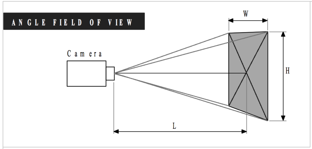
The focal length can be calculated adequately by the following formula if the distance between a camera and a subject and widths of the subject are found.

How to decide the shooting area.
The shooting area can be calculated by the following formula with the focal length (mm) of Lens.
(Width of picture)

(Height of picture)

The shooting area and size depend on the focal length. It is very important to select adequate Lens to meet the shooting purpose
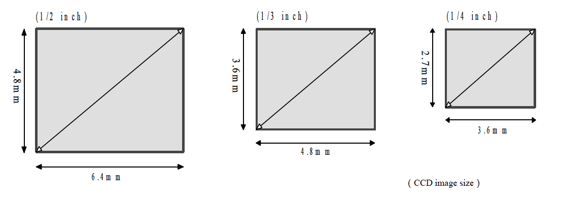
*Due to the downsizing camera, CCD image size became smaller. Now there are three types of CCD, 1/2, 1/3, and 1/4 inch, in our products.
Each angle of view is as follows
Fixed Lens
It is also called “Fixed Focal Length Lens.” Since the focal length is always fixed, the angle of view does not vary. It is classified as below in accordance with the focal length.
- Super-wide-angle Lens(f = 2.5mm more or less)
- Wide-angle Lens(f = 4~6mm more or less)
- Standard Lens(f = 8~12mm more or less)
- Telephoto Lens(f = 36mm more or less)
- Super-telephoto Lens(f = 50mm more or less)
Manual Iris / Auto Iris Lens
“Iris” controls a quantity of light complying with the variation of illuminance. The brightness of Lens can be expressed by f/number, and here it stands for the ratio of effective Lens bores.
F/number = Focal Length / Lens Bore
The smaller f/number, the Lens becomes “Light Lens” at a same focal length.
WAT-A96002I (C-mount) f12mm, F1.4
WAT-1220BC-5 (Miniature lens) f12mm, F2.0
When the brightness is constant, you can select and use a Manual Iris Lens. However, if the brightness varies over time, an Auto Iris Lens is recommended.
Auto Iris Lens
“Video Iris Lens,” one of the Auto Iris lenses, self-contains an Iris Control Amp (EE Amp). All our products are classified in this type. To control the Iris automatically, Iris is closed when the video signal is judged a greater level, and Iris is opened if it is smaller. That is, Auto Iris Lens keeps the adequate correct exposure automatically so that the video signal from camera can keep at a constant level.
There are two types of method, “Average Value Detection” and “Peak Value Detection,” to detect the video signal level. The Average Value Detection system detects the average of brightness in whole video screen and controls it. Peak Value Detection system detects a signal that shows the brightest condition in whole wide screen and controls it. On the other hand, Video Iris Lens needs to be calibrated the sensitivity.
| * ALC (Auto Level Control) Calibration for brightness detection system |
|||
| Monitor Screen | Rotating direction of ALC | ||
| When a part of screen (high-illuminace portion) is fogged by halation | Turn it to Pk direction | ||
| When whole screen becomes dark except high-illuminace portion | Turn it to Av direction | ||
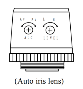
| * Calibration for LEVEL sensitivity | ||
| Monitor screen | Rotating direction of LEVEL volume | |
| Brighter | Turn it to H (High) direction | |
| Darker | Turn it to L (Low) direction | |
DC Iris Lens
DC Iris Lens does not equip Iris Control Amp (EE Amp) in Lens, and controls the Iris by applied driving power from camera.
(Our WATEC camera does not match with any DC Iris Lens.)
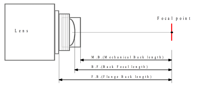
Flange Back / Back Focus / Mechanical Back
Flange Back is the distance between fiducial face (Flange) of mounting Lens and focused face, and has C-mount and CS-mount
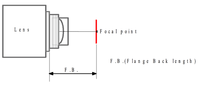
*C-mount Lens is mainly available for 1/2″ CCD camera.
C-mount(Flange)= 17.526mm (for 1/2 inch CCD camera)
*CS-mount Lens is mainly available for 1/3″ CCD camera, but recently both are acceptable by applying C-mount adaptor or flange back adjustment
CS-mount (Flange) = 12.526mm (for 1/3inch CCD camera)
*Back Focus
Back Focus is a distance between the top of Lens face and focused face. It is helpful not to occur interference between the tail of camera and mechanical parts in the camera mount, when you mount the Lens on camera
Varifocal Lens
Variofocal Lens has a manual scaling function and enables to decide the focal length manually. After setting the angle of value by zoom and focus, adjust the focus of the Lens applying some adjustment for Flange Back
When you set a camera, you can choose an adequate focal length to be able to show out the subject as your favorite size while watching the monitor screen.
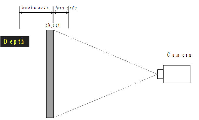
Depth
When focusing on a subject, there is a range in front of and behind the subject that can also be in focus. This range is called “Depth.” Only objects within this range (or depth) can be in focus. Iris has some important functions. It not only determines the amount of exposure but it also determines the depth of focus.
| The greater Iris number (That is, stopping the lens down), the deeper the Depth becomes. | ||
| If several Iris Lenses have the same number, the brighter the lens is, the wider the depth becomes. | ||
| Telephoto Lenses do not have wide-range of depth. But a Wide-angle Lens dose have a wide-range of depth.(The depth differs between utilizing Telephoto and Wide-angle even if Zoom Lens is set up to the camera.) | ||
| For a subject that has greater depth, the depth becomes small at the front area of the subject. | ||
| On the contrary, the depth becomes bigger at the back area of the subject. | ||